
Disclaimer: This article is more than two years old. Developments in science and computing happen quickly, and more up-to-date resources on this topic may be available.
In This Issue:
- From the Director
- Lab Impact: Workflow in Complex Simulation Codes
- Collaborations: Using Uncertainty Quantification Tools to Help Accelerate the Development and Deployment of Carbon Capture Technologies
- Advancing the Discipline: Parallel Discrete Event Simulation: When Differential Equations Just Won't Cut It
- Path to Exascale: Unify: Breaking the I/O Bottleneck in Exascale Architectures
- Highlights
From the CASC Director
The Sidney Fernbach Postdoctoral Fellowship in the Computing Sciences was established in 2012 to attract top new researchers into the Computation Directorate. Similar to LLNL's Lawrence Fellowship, it offers outstanding new scientists the opportunity to establish their own research directions with a great deal of autonomy. The Lawrence Fellowship is open to all technical disciplines at the Laboratory and is awarded to several candidates each year. The Fernbach, on the other hand, focuses specifically on disciplines in the computing sciences: applied mathematics, computer science, computational science, and data science. It usually supports one fellow at a time for a two-year term.
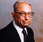
The fellowship was named for Sidney Fernbach (pictured), who founded the Computing Department at LLNL in 1952 and ran it until 1982. We have completed three application cycles since the fellowship began. In the inaugural year, we made three offers. None were accepted, although one candidate became a Lawrence Fellow instead. Lesson learned: We needed to finish the process sooner to compete with other opportunities available to outstanding recent doctoral graduates. Our second solicitation brought us our first fellow, Hormozd Ghavari, who did distinguished work in performance modeling of numerical algorithms at scale. Sadly, Hormozd passed away in 2016 after a long and courageous battle against Ewing’s sarcoma. Our current fellow is Nikhil Jain. Nikhil’s work has focused on modeling the performance of large parallel applications, especially the influence of network topologies and interactions with other applications. As a fellow, he has been extraordinarily productive, publishing nine peer-reviewed papers just in 2017!
As we begin 2018, we are in the middle of our fourth season of selection for the Fernbach. The application process started in August 2017, and candidates have applied from around the world (the deadline was in November). We expect to name a new fellow in the spring. While the interests and backgrounds of the candidates are broad, a common theme in many of the letters of reference is that their mentors view the candidates as colleagues rather than apprentices. Such praise speaks highly of the candidates’ research maturity, independence, and professionalism, and we look forward to welcoming our next fellow.
Sign up to be notified of future newsletters.
Contact: John May
Lab Impact | Workflow in Complex Simulation Codes
Workflow in the context of simulation is a term used to capture the entire process of using application codes and computers in pursuit of our mission goals. Before a simulation is ever run on a high performance computer, an expert or team of experts must model the system by setting up the problem inputs. After a simulation is run, that same expert or team must analyze the results in order to turn the raw data into actionable information. During a simulation run (which in some cases can span weeks or months) the user must manage large data sets, monitor progress, and adjust course as necessary. It is this conception-to-conclusion series of steps that we refer to as the user workflow, and making users of our simulation tools efficient and productive along that path can be just as important as speeding up the core simulation on resources like those available at LLNL.
The Workflow project, led by Dan Laney in CASC in support of LLNL's ASC mission, is focused on enabling an ecosystem of tools that users can draw on to construct workflows, manage and analyze simulation information, and leverage next-generation analytics capabilities. The project currently has three main efforts which are highlighted here: Siboka focused on data & workflow management, C2C on problem setup, and ROVER on in-situ diagnostics.
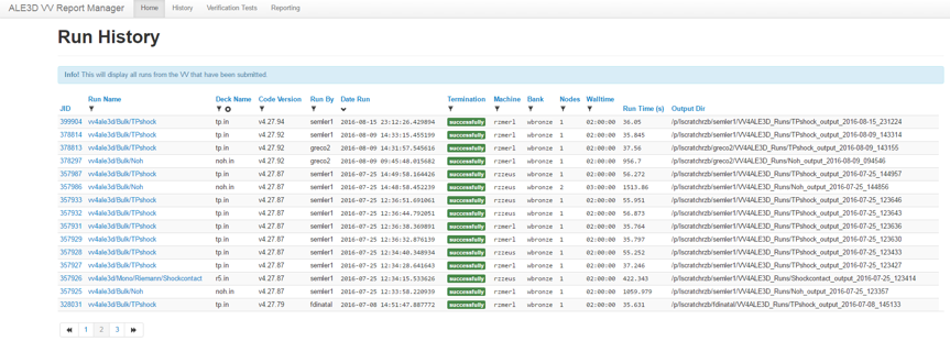
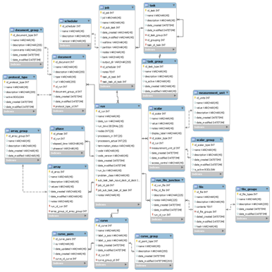
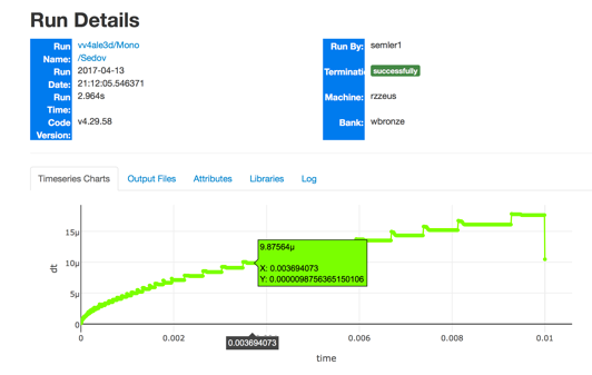
Siboka is a set of Python components supporting simulation information collection, data management & analysis, and simulation management. This past year the team developed and deployed a web-based application called VV4ALE3D that enables both workflow automation and reporting/analysis of results for a subset of the ALE3D Verification and Validation (V&V) suite. This effort is motivated by the extensive use of simulation suites in the WCI community to guide code development and enable validation. VV4ALE3D allowed the team to integrate tools previously developed for extracting information from simulation runs, and store them in a common database with those used for managing runs and displaying results. The application is integrated with the Livermore Computing (LC) web-based Lorenz (or myLC) infrastructure and APIs which enable it to interact with LC compute resources and schedulers. The simulation information management tools underpinning VV4ALE3D are being productized in Sina (simulation insight & analysis), a python package bringing together database support with querying and analysis. Finally, the project open-sourced a lightweight serverless workflow manager called Maestro , that enables specification of workflows and management of their execution with minimal infrastructure. With day-to-day production use of VV4ALE3D now a reality, plans are in place to generalize the tool to support additional simulation codes and suites.
The C2C (Contours to Codes) project's aim is make it easier and less error-prone for WCI users to share the results of the time-intensive process of setting up simulation geometries. Contours are geometric descriptions of curves and surfaces that provide much of the basis for embodying a description of a mechanical part or system being modeled into a discretized mesh representation suitable for use by a simulation code, and are often transcribed directly from original blueprints or drawings to ensure provenance. The C2C team has developed a parser for a neutral contour format designed to efficiently represent problem setup information, and a set of tools for working with contours and converting between the contour format and other formats. The C2C tools work with the LLNL's workhorse parallel meshing tool PMESH to enable problem setup and conversion between multiple code input formats. Efforts are underway to extend the C2C tools and to develop a repository database of validated contours that will enable community-wide sharing of validated problem setup information.
Finally, ROVER is focused on building a GPU accelerated ray tracing package capable of doing multi-group radiography, both back-lit and with self-emission, as well as serving as a volume rendering plot in VisIt and other VTK-based (Visualization Toolkit) visualization tools. The long-term goal is a package with in-situ capability, or the ability for diagnostic images to be rendered by the simulation and viewed in real-time, instead of as a file-based post-processing step. ROVER components are being integrated into the open source VTK-m library (also supported by the DOE Exascale Computing Project) and the capability will be available in a future VisIt release.
The workflow team works closely with other teams providing setup and analysis tools in support of the ASC Program, and together are working toward enabling new capabilities for exascale computing and large-scale analytics, and increased efficiencies and productivity for ever-increasingly complex workflows.
The workflow team includes Kathleen Dyer, Joe Eklund, Rebecca Haluska, Nathan Greco, Esteban Pauli, and Jessica Semler, all from the ASQ division in Computation, and Ghaleb Abdulla and Ming Jiang from CASC.
Contact: Dan Laney
Collaborations | Using Uncertainty Quantification Tools to Help Accelerate the Development and Deployment of Carbon Capture Technologies
A viable approach to reduce the emission of greenhouse CO2 gas into the atmosphere is to retrofit existing coal-burning power plants with cost-effective carbon capture capabilities. However, the development and deployment of effective and efficient carbon capture technologies have been hampered by the long lead time from new concepts to industrial deployment, and the high cost of pilot projects. It was recognized that new approaches based on advanced modeling and simulation have the potential to dramatically reduce the development time. In response to these needs and opportunities, a partnership was formed among five national laboratories, industry and academic institutions in 2010 with the goal of developing and deploying state-of-the-art computational modeling and simulation tools to accelerate the commercialization of carbon capture technology from discovery to development, demonstration, and widespread deployment to existing power plants - a project now known as the Carbon Capture Simulation Initiative (CCSI), which has been supported by the US Department of Energy's Office of Fossil Energy.
A major product of CCSI is a simulation toolset and infrastructure comprising data, models, software, and best practices. While LLNL has played multiple roles in CCSI, its key involvement has been in the development of mathematical, statistical, and computer science tools for quantifying uncertainties in simulation models. Uncertainty Quantification (UQ) was recognized as important in the early project development stage, but soon it was realized that UQ was ubiquitous in all aspects of the multi-physics (multi-phase flow, chemistry, etc.) and multi-scale (particle, device and process scales) modeling and optimization process. As such, systematic methodologies have to be developed to propagate and manage uncertainties across all scales, taking into account uncertainties due to parametric uncertainties, model deficiency, operating and data noises at various stages.
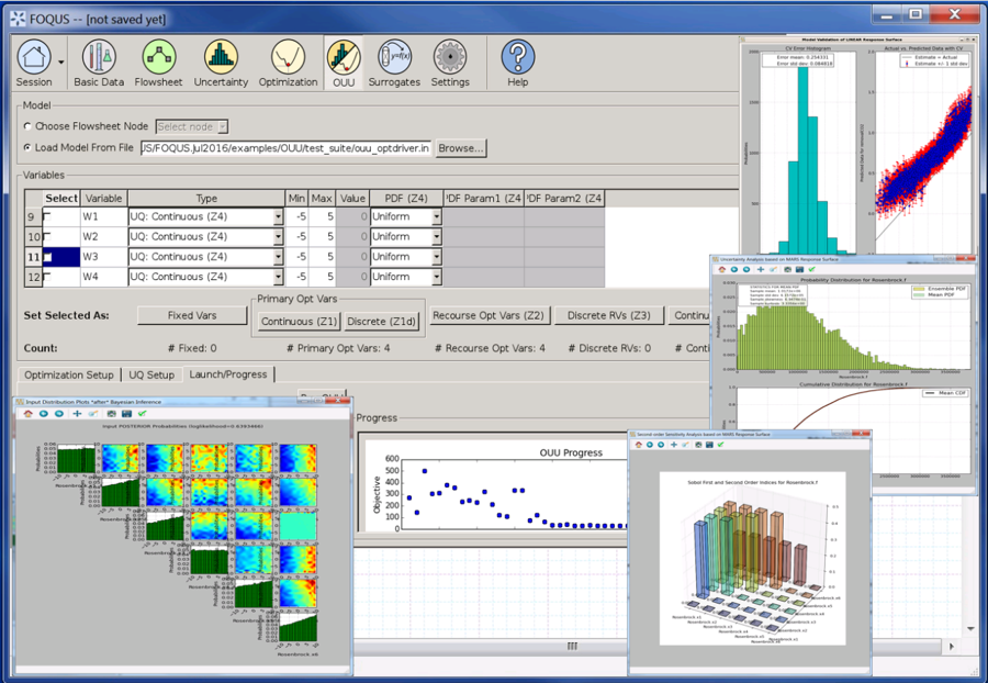
In the course of the project cycle, it became clear that there was a need to develop an integrated framework for handling the complex simulation workflows, UQ, and design optimization. As such, a CCSI software project called FOQUS (Framework for Optimization and Quantification of Uncertainty and Sensitivity) was conceived. FOQUS integrates simulation models for carbon capture with advanced process optimization and UQ tools to help identify the best potential carbon capture processes and quantify the level of uncertainties associated with different process configurations. Embedded underneath the exotic FOQUS graphical user interface is its computational workhorse - the PSUADE (Problem Solving environment for Uncertainty Analysis and Design Exploration) software library, which provides capabilities for uncertainty analysis, sensitivity analysis, response surface analysis, Bayesian inference, optimization under uncertainty, experimental design, etc. FOQUS is also powered by another CCSI software tool called Turbine (developed at LBNL) to run UQ ensemble calculations.
Ongoing work includes multi-objective optimization under uncertainty, sequential design of experiments, and application of FOQUS to newly-developed carbon capture models.
For additional information on the toolset developed for the CCSI, see this article published in LLNL's Science & Technology Review.
Contact: Charles Tong
Advancing the Discipline | Parallel Discrete Event Simulation: When Differential Equations Just Won't Cut It
As is often evidenced in the pages of this newsletter and much of the R&D that CASC pursues, simulation is an essential tool in many research fields, standing as an equal alongside experiment and theory. However, many science domains do not have an underlying physical theory expressible as systems of differential or algebraic equations. In these cases, discrete event simulation (DES) is used as a means to model and disentangle correlation and causation, explore possible alternate realizations not available in physical form, and demonstrate emergent phenomenon and other effects not amenable to theory.
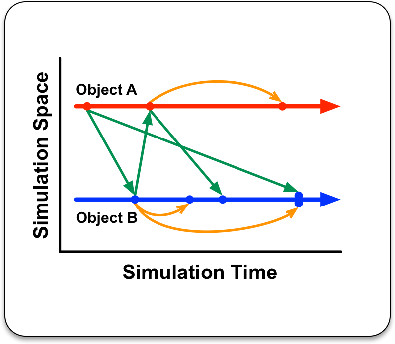
Discrete event simulation decomposes a problem into separate "logical processes" (LPs), sometimes called agents or nodes, which interact by sending time-stamped messages, or events. LPs have internal state, which in turn evolve during the course of the simulation in response to processing messages. Each message identifies an action the LP should take, perhaps in the form of function pointer and any arguments needed, along with the simulation time at which the LP should take that action. In the course of executing an event an LP can update its state, as well as send (or cancel) other event messages. Events to self, out of order events, as well as event ties are all allowed. Of course, sending events into the past is forbidden, as that would violate causality.
In DES, there is a strong separation between the simulator and the model being simulated. The job of the simulator is to execute events in time stamp order until there are no more events to execute or a model-designated stop time or stopping condition is met. The model in turn represents information specific to the domain being studied, such as computer networking traffic or the evolution of virus outbreaks in a population. This separation of concerns is analogous to the separation between a numerical solver library and a domain-specific continuum model in traditional differential equation-based applications.
Naturally researchers want to explore larger and larger problems, requiring more computing power and memory than available on a single system, necessitating parallel DES (or PDES). Because there can only be one timeline with events executing in a specific order, and the ordering of events cannot be predicted a priori since they are dynamically generated as the simulation unfolds, the single most challenging problem in PDES is synchronizing the execution across many simulation processes in a computing cluster. Each process simulates a portion of the entire model, yet the overall execution must obey causality and reproduce the exact result which a sequential (single computer) execution would have produced.
Historically there have been two approaches to the synchronization problem, conservative or optimistic execution, with different requirements and constraints the model must adhere to. Not surprisingly some kinds of models perform better with one approach versus the other, and this distinction may not be known up front - or may even vary within a simulation over time. Until recently, model writers have had to make a static global choice of parallel synchronization approach, and thus the simulator upon which to run their model.
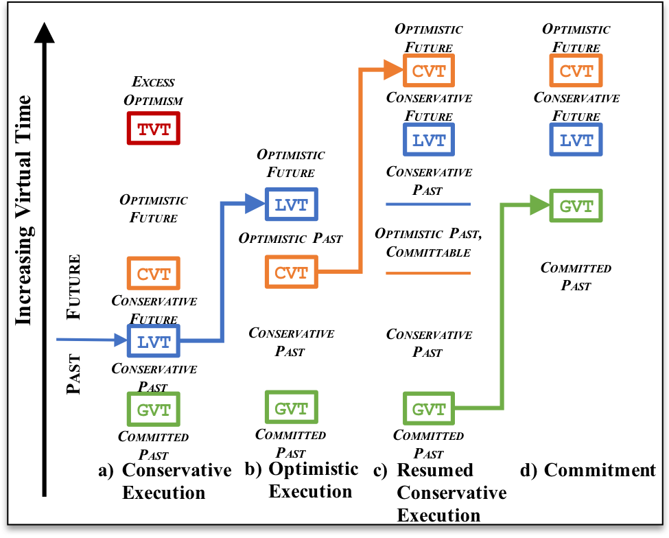
CASC researchers David Jefferson and Peter Barnes recently spearheaded the development of Unified Virtual Time, a mechanism which enables the simulator to choose dynamically whether to execute the next event optimistically or conservatively, and make this choice separately at each LP. Figure 6 illustrates the behavior of one LP, from the simulator perspective, during the course of execution; using the terminology from the paper [1]. At various times the simulator is executing events either conservatively or optimistically, based on the value of a control variable CVT, which is updated asynchronously. Switching back and forth between conservative and optimistic execution leaves behind different spans of past events which the simulator then correctly manages.
The significance of this unification is that it enables the model writer to concentrate on what they know best: the desired agents, actions, and messages needed to represent their problem, and let the simulator be entirely responsible for executing the model as fast as possible. This separation of concerns is made much easier by our prior development of Backstroke [2], a code generation framework leveraging the ROSE compiler toolkit developed in CASC, which automatically transforms sequential model code into a reversible form suitable for optimistic synchronization.
We are currently expanding our theory into a journal submission, and expect to implement and test these ideas in practice in the coming months. Check back in future newsletters for articles describing how the PDES simulation techniques described here have enabled specific models to solve complex problems of interest to DOE, the DoD, and others.
Contact: Peter Barnes
[1] D. Jefferson and P. D. Barnes Jr., Virtual Time III: unification of conservative and optimistic synchronization in parallel discrete event simulation, in proceedings of the Winter Simulation Conference 2017 Reno, Nevada.
[2] M. Schordan, et al., Automatic Generation of Reversible C++ Code and Its Performance in a Scalable Kinetic Monte-Carlo Application, in proceedings of PADS 2016: ACM SIGSIM Conference on Principles of Advanced Discrete Simulation (PADS), (Banff, Canada, May 15–18, 2016), p. 111.
The Path to Exascale | Unify: Breaking the I/O Bottleneck in Exascale Architectures
The view of storage systems for HPC is changing rapidly. Traditional, single-target parallel file systems have reached their cost-effective scaling limit, and multi-target, hierarchical storage systems are being designed and installed for our nation’s next-generation and exascale leadership class systems such as the Sierra system currently being stood up at LLNL. We expect the first-level target of hierarchical storage for future exascale HPC systems to be compute-node local storage, e.g., SSDs or NVRAM. This distributed, node-local storage design promises fast, scalable I/O performance because storage bandwidth and capacity will automatically scale with the compute resources used by jobs and workflows and won’t suffer from inter-job interference common with shared storage resources like the parallel file system or shared burst buffers. However, a major concern for this distributed design is how to present the disjoint storage devices as a single storage location to applications that use shared files.
To support hierarchical storage of exascale systems, we are developing the Unify framework. Our goal with Unify is to deliver transparent, blazing-fast I/O performance over distributed first-level storage. Unify is a framework that supports a suite of user-level file systems that can be flexibly loaded into users’ job allocations, where each file system is highly-specialized for a particular I/O workload. For example, one specialized Unify file system (UnifyCR) targets write-heavy, bulk-synchronous I/O workloads, typical of checkpoint/restart or periodic output by HPC applications, while another Unify file system is tailored for read-heavy workloads common in machine-learning applications. The key factor behind delivering a suite of file systems instead of a single general-purpose file system is performance. General-purpose file systems must support the strictest consistency semantics, e.g., imposing expensive locks around I/O operations. Ensuring general semantics and strict consistency greatly reduces performance when the workload does not require them. For example, for checkpoint/restart workloads, write and read phases are disjoint and processes do not write to the same file offset in a shared file. Thus, in UnifyCR, we eliminate locking and delay visibility of file data across distributed storage until the end of the write phase, resulting in more than 2X speedups over the state-of-the-art in shared write performance in our experiments.
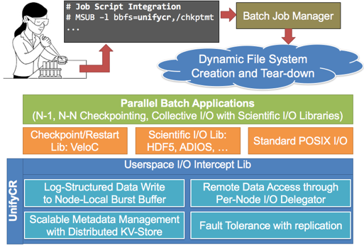
Unify file systems are ephemeral, with the same lifetime as an HPC job. Unify file system instances are launched at the beginning of a batch job, provide data services for all applications in the job, and terminate at the end of the job allocation. Figure 7 shows the system architecture of Unify using UnifyCR as an example. A user can request one or more Unify file systems to be loaded and respective mount points in their batch script (UnifyCR on /chkptmt in the figure). Then, applications in the allocation can leverage Unify to share files simply by directing I/O operations to the Unify mount point, e.g., /chkptmt. Additionally, applications within the same job allocation (e.g., restarts after failure or separate application components) will be able to share data and storage on the same Unify file system instance, which can greatly reduce the need of back-end persistent file systems for data sharing across these programs.
Project members include CASC personnel Kathryn Mohror and Kento Sato, Livermore Computing collaborators Adam Moody, Danielle Sikich, and Ned Bass, as well as external collaborators from Florida State University and Oak Ridge National Lab.
Contact: Kathryn Mohror
CASC Highlights
Awards
- Abhinav Bhatele, Jae-Seung Yeom, Nikhil Jain, and others won a 2017 NERSC Award for Innovative Use of HPC.
- Dean Williams, Sasha Ames, Charles Doutriaux, Renata McCoy, Matthew Harris, William Hill, Jason Boutte, Zeshawn Shaheen, Denis Nadeau, Tony Hoang, and Jeff Painter won an R&D 100 Award for the Earth System Grid Federation software, which helps scientists around the world manage, disseminate, and analyze earth system science data.
- Brian Van Essen and external collaborators won an HPCwire Editor's Choice Award for Best Use of AI for the CANDLE project, which applies machine learning to personalized cancer medicine.
- Roger Pearce won an IEEE High Performance Extreme Computing Conference Graph Challenge Champion award.
Looking back...
December's calendar was filled with holiday parties for CASC employees, as it has been for many years. In the past, a premier event was the Lab Director's Office party. This invitation-only gala was attended mainly by managers and other senior staff. It was held at elegant off-site locations with live music and dancing. Guests wore formal attire and paid a significant amount for their tickets. Today, the Director's holiday party is far more egalitarian. It's held at several locations onsite, and all employees are invited.

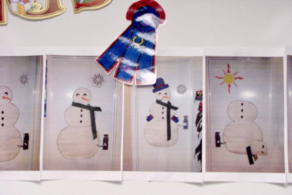
Fifteen years ago, then-Associate Director Dona Crawford hosted an onsite celebration for Computation that featured extensive decorations and carolers in costume, above. (Judging by their badges, they were non-employees brought in for the event.) The White Room was adorned with photos from a door-decorating contest, where employees had dressed up their office entrances with snowmen and other holiday items, below.
These days, CASC holds its holiday parties at a private residence near the lab (which happens to be the home of the Acting CASC Director). Employees bring spouses and children, and the food includes pizza and desserts. No formal attire is required. However you celebrated the holidays, at work and at home, we hope you had a restful and cheerful break, and we wish you the best for the new year!
Newsletter Sign-up
Sign up to be notified of future newsletters.